
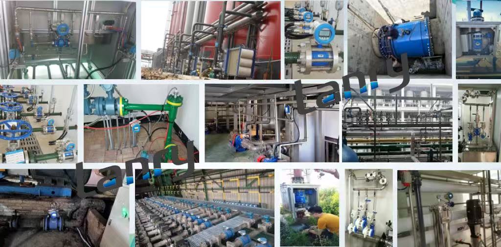
Electromagnetic flow meters (EM meters) are widely used in industrial, municipal, and water treatment applications for their high accuracy, ability to handle conductive fluids, and minimal pressure drop. However, their performance is heavily dependent on proper installation—even the most advanced EM meter will fail to deliver reliable data if installed incorrectly. From pipeline conditions to environmental factors, several critical elements must be addressed to ensure optimal functionality. This article outlines the key considerations for installing EM meters in pipeline systems.
1. Pipeline Straight Length Requirements
Most manufacturers recommend a minimum of 5 times the pipe diameter (5D) of straight pipe upstream of the EM meter and 3 times the pipe diameter (3D) downstream. For example, if installing a meter in a 4-inch (100mm) pipeline, there should be at least 20 inches (500mm) of straight pipe before the meter and 12 inches (300mm) after. In cases where space is limited (e.g., tight mechanical rooms), installing flow conditioners (such as straighteners or perforated plates) can reduce the required straight length by stabilizing the flow profile. Avoid installing the meter immediately after pumps or control valves, as these components generate significant turbulence.
2. Pipe Size and Meter Compatibility
- Do not undersize the meter: An undersized meter creates a narrow flow path, increasing fluid velocity and pressure drop. This can damage the meter’s lining over time and cause false high-flow readings.
- Do not oversize the meter: An oversized meter results in low fluid velocity, especially at low flow rates. Since EM meters rely on consistent velocity to generate a measurable electromagnetic signal, low velocity can lead to unstable readings or failure to detect flow entirely.
If the pipeline size does not align with standard EM meter sizes (e.g., a 5-inch pipeline with no matching meter), use reducers or expanders installed at least 10D upstream of the meter to transition between sizes. Ensure reducers are concentric (not eccentric) to avoid creating uneven flow distribution.
3. Fluid Fill and Installation Orientation
- Horizontal installation: The preferred orientation for most applications. Mount the meter so that its electrodes are positioned at 45° to 90° from the bottom of the pipe (not directly at the bottom). This avoids electrode contact with sediment or debris that settles at the pipe’s base, which can cause fouling. It also prevents air pockets from collecting near the electrodes (air tends to rise to the top of horizontal pipes).
- Vertical installation: Suitable for applications with upward fluid flow (never downward, as this can trap air at the meter). Vertical installation ensures the pipe is always full and helps prevent sediment buildup. However, confirm the meter is rated for vertical mounting—some models have weight or flow direction restrictions.
- Avoid installation at pipe peaks: Installing the meter at the highest point of a pipeline increases the risk of air pockets. If unavoidable, add air vents upstream of the meter to release trapped gas.
4. Material Compatibility and Environmental Protection
- Wetted parts: For corrosive fluids (e.g., acidic wastewater, chemical solutions), use linings like PTFE (Teflon) or FKM (Viton) and electrodes made of Hastelloy C or titanium. For abrasive fluids (e.g., sludge with solids), choose reinforced linings (polyurethane) to resist wear. For potable water, ensure materials meet NSF/ANSI 61 or WRAS standards to avoid contamination.
- External housing: In harsh environments (e.g., outdoor installations, industrial facilities with dust or moisture), select meters with an IP (Ingress Protection) rating of at least IP65 (dust-tight and protected against low-pressure water jets). For submersible applications (e.g., underwater pipelines), use IP68-rated meters. In explosive environments (e.g., oil refineries), choose meters with ATEX or IECEx certifications for hazardous locations.
5. Electrical Grounding and Interference Prevention
- Meter grounding: Connect the meter’s grounding terminal to a dedicated, low-resistance ground (≤10Ω). Do not share the ground with other equipment (e.g., motors, pumps), as this can introduce noise. For plastic pipelines (which are non-conductive), install a ground ring (a metal ring attached to the pipe upstream and downstream of the meter) and connect it to the meter’s ground. This ensures the fluid is at the same ground potential as the meter.
- Cable management: Use shielded cables for power and signal transmission (e.g., 4-20mA analog cables, RS485 digital cables). Route cables away from high-voltage lines (e.g., 380V power cables) and electromagnetic sources (e.g., variable frequency drives, motors) to avoid interference. Maintain a minimum distance of 1 meter between EM meter cables and high-noise cables.
6. Accessibility for Maintenance and Calibration
- Provide clear access: Ensure there is at least 1 meter of space around the meter for technicians to work. If the meter is installed at height, use platforms or ladders (with safety features) for access.
- Valve placement: Install isolation valves upstream and downstream of the meter. These valves allow technicians to shut off fluid flow for maintenance or replacement without stopping the entire pipeline system. Use full-port valves to avoid restricting flow when open.
- Calibration considerations: Choose a location that allows easy connection to calibration equipment (e.g., portable flow standards). For large pipelines, ensure there is space for calibration tools to be installed temporarily.
Conclusion
Post time: Oct-11-2025