
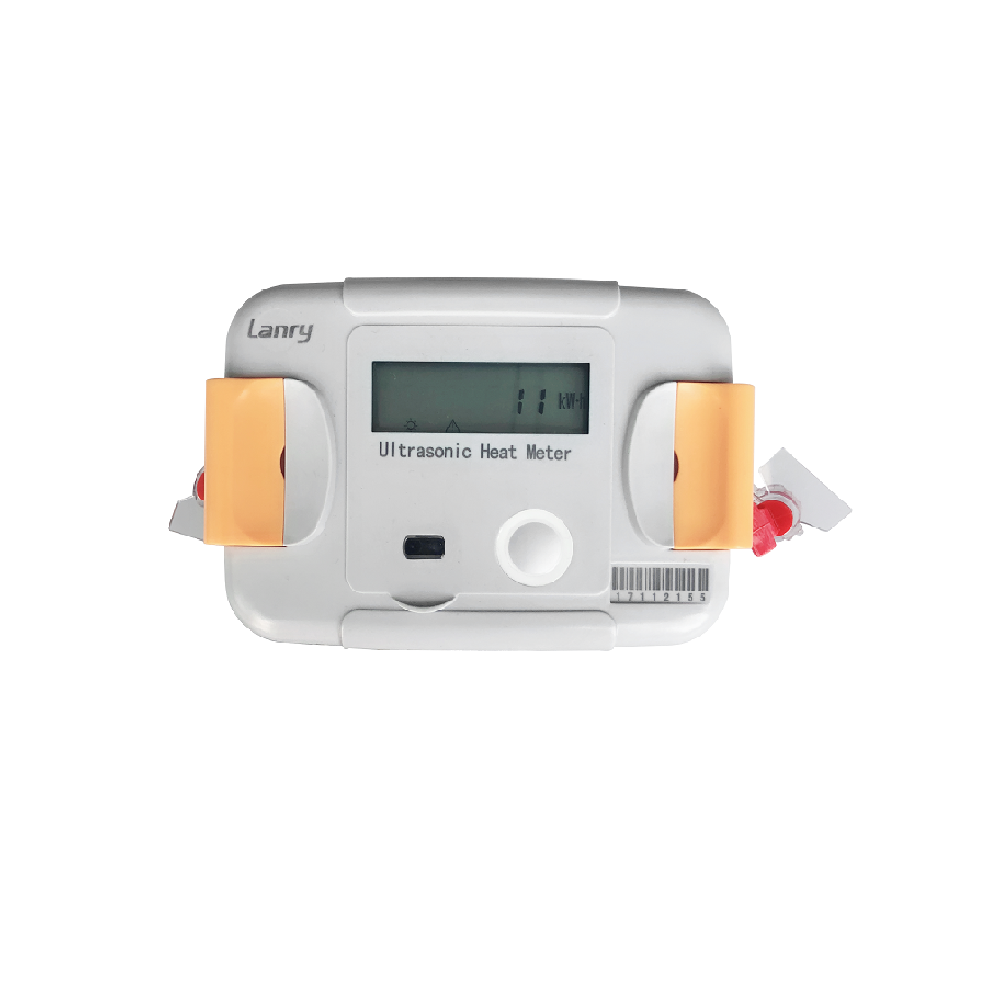
RC82 Series ultrasonic heating (cooling, heating-cooling) meters are used for energy measurement of heating or chilled water in residential and small commercial heating and air conditioning systems. They are available in DN15-40 and have an electronic energy calculator with separate register for heating and cooling energy. They are fitted with an M-Bus interface for integration into M-Bus networks.
Features

Internal 3.6V lithium battery power supplying;
Calculator case's unique design, users can meet multi-angle data is read;
Support supply water and backwater pipeline position installation to satisfy users different requirements.
Support level and vertical installation to satisfy users’ different requirements.
Support optical interface, RS485 interface and M-Bus interface etc. multi-communication mode, easy for centralized data management by user.
NOWA-testing in the parallel mode is applicable.
Technical Data
Profile
| Application | Heating/cooling/heating-cooling metering |
| Approval | MID |
| Mount position | Vertical or horizontal |
| Calculator protection class | IP 65 |
| Battery supply | 3.6V lithium battery up to 8 years lifetime |
| Temperature sensor type | PT1000 |
| Cable length of temperature sensor | 1.5 meter (or customized) |
| Test possibilities | display, instruction (compatible with NOWA software) |
Calculator basic features
| Environmental class | EN1434/MID E1+M1 |
| Ambient operating temperature | A Class (5~55) ℃ or B Class(-25 ~ +55) ℃ optional |
| Ambient storage temperature | -20~ +70 ℃ |
| Protection class | IP 65 |
| Radio system | Wireless M-bus can be integrated by 868,434,169MHz (OMS) |
| Standard interface | Optical interface |
| Interfaces optional | 1 Slots for modules with M-Bus, RS485, Pulse Output |
| Temperature range heating | 4~95℃ |
| Temperature range cooling | 4~95℃ |
| Extensive data memory | 720 days flow data and heat data |
| RS485 communication | red is vcc(5~24VDC),white is B,green is A,black is GND |
| Pulse output | red is output and black is GND |
Display
| Display indication | LCD, 8 digits |
| Units | MWh - kWh - GJ - Gcal - ℃ –K - m³ - m³/h |
| Total values | 99,999,999 - 9,999,999.9 - 999,999.99 - 99,999.999 |
| Values displayed | Energy /Power/Volume/ Flow Rate/Temperature and more |
Interfaces
| Optical | Band rate 2400 |
| M-Bus | Band rate 300-9600 |
| RS485 | Band rate 300-9600 |
| Pulse output | One pulse output |
Temperature input
| Starting temperature difference ∆Θ K | 0.25 |
| Min. temperature difference ∆Θmin K | 3 (2K can be customized) |
| Max. temperature difference ∆Θmax K | 60 (105 can be customized) |
| Absolute Temperature measuring range Θ ℃ | 4 ~95 (4-130 can be customized) |
Dimension
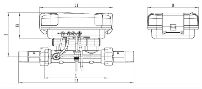
| Nominal Flow rate | Qp | m3/h | 0.6 | 0.6 | 0.6 | 1.5 | 3.5 | 6 | 6 | 10 |
| Nominal Diameter | DN | mm | 15 | 20 | 20 | 15 | 25 | 25 | 32 | 40 |
| Body Length | L | mm | 110 | 130 | 190 | 110 | 160 | 260 | 180/260 | 200/300 |
| Overall Length | L2 | mm | 200 | 230 | 290 | 200 | 260 | 360 | 280/360 | 300/400 |
| Calculator Length | L1 | mm | 150 | 150 | 150 | 150 | 150 | 150 | 150 | 150 |
| Height | H | 100 | 103 | 103 | 100 | 106 | 106 | 109 | 113 | |
| Calculator Height | H1 | 60 | 60 | 60 | 60 | 60 | 60 | 60 | 60 | |
| Calculator Width | B | 105 | 105 | 105 | 105 | 105 | 105 | 105 | 105 | |
| Screw thread on meter | inch | G3/4B | G1/4B | G1B | G3/4B | G1 1/4B | G1 1/4B | G1 1/2B | G2B | |
| Screw thread on coupling | inch | R1/2 | R3/4 | R3/4 | R1/2 | R1 | R1 | R1 1/4 | R1 1/2 | |
| Working pressure | Mpa | 1.6/2.5 | ||||||||
| Qp: Qi | 50:1, 100:1, 250:1 | |||||||||
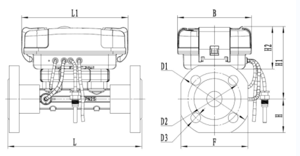
| Nominal Flow rate | Qp | m3/h | 0.6 | 1 | 1.5 | 2.5 | 3.5 | 6 | 6 | 10 |
| Nominal Diameter | DN | mm | 20 | 20 | 20 | 20 | 25 | 25 | 32 | 40 |
| Overall Length | L | mm | 190 | 190 | 190 | 190 | 260 | 260 | 260 | 300 |
| Calculator Length | L1 | mm | 150 | 150 | 150 | 150 | 150 | 150 | 150 | 150 |
| Height | H | 47.5 | 47.5 | 47.5 | 47.5 | 52.5 | 52.5 | 62.5 | 70 | |
| Height 1 | H1 | 103 | 103 | 103 | 103 | 106 | 106 | 109 | 109 | |
| Calculator Height | H2 | 60 | 60 | 60 | 60 | 60 | 60 | 60 | 60 | |
| Calculator Width | B | 105 | 105 | 105 | 105 | 105 | 105 | 105 | 105 | |
| Flange Diameter | F | mm | 95 | 95 | 95 | 95 | 105 | 105 | 125 | 140 |
| Flange Diameter | D1 | mm | 105 | 105 | 105 | 105 | 115 | 115 | 140 | 150 |
| Hole circle diameter | D2 | mm | 75 | 75 | 75 | 75 | 85 | 85 | 100 | 110 |
| Screw hole diameter | D3 | mm | 14 | 14 | 14 | 14 | 14 | 14 | 18 | 18 |
| Number of screw holes | pcs | 4 | 4 | 4 | 4 | 4 | 4 | 4 | 4 | |
| Working pressure | Mpa | 2.5 | 2.5 | 2.5 | 2.5 | 2.5 | 2.5 | 2.5 | 2.5 | |