
Installation on larger pipes requires careful measurements to the linear and radial placement of the L1 transducers. Failure to properly orient and place the transducers on the pipe may lead to weak signal strength and/or inaccurate readings. The section below details a method for properly locating the transducers on larger pipes. This method requires a roll of paper such as freezer paper or wrapping paper, masking tape and a marking device.
1. Wrap the paper around the pipe in the manner shown in Figure 2.4. Align the paper ends to within 6 mm.
2. Mark the intersection of the two ends of the paper to indicate the circumference. Remove the template and spread it out on a flat surface. Fold the template in half, bisecting the circumference. See Figure 2.5.
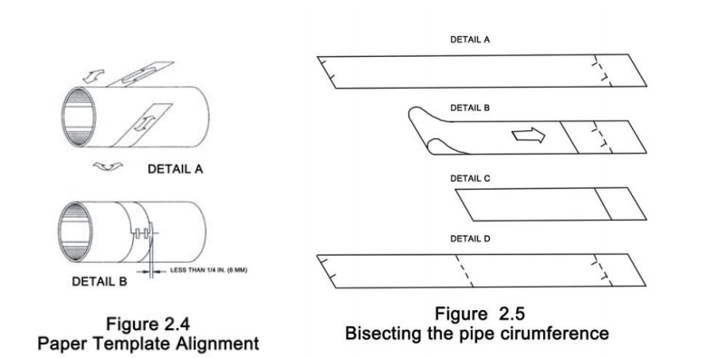
3. Crease the paper at the fold line. Mark the crease. Place a mark on the pipe where one of the transducers will be located. See Figure 2.1 for acceptable radial orientations. Wrap the template back around the pipe, placing the beginning of the paper and one corner in the location of the mark. Move to the other side of the pipe and mark the pipe at the ends of the crease. Measure from the end of the crease directly across the pipe from the first transducer location) the dimension derived in Step 2, Transducer Spacing. Mark this location on the pipe.
4. The two marks on the pipe are now properly aligned and measured.
If access to the bottom of the pipe prohibits the wrapping of the paper around the circumference, cut a piece of paper to these dimensions and lay it over the top of the pipe.
Length = Pipe O.D. x 1.57; width = Spacing determined on page 2.6
Mark opposite corners of the paper on the pipe. Apply transducers to these two marks.
5. Place a single bead of couplant, approximately 1.2 mm thick, on the flat face of the transducer. See Figure 2.2. Generally, a silicone-based grease is used as an acoustic couplant, but any grease-like substance that is rated to not “flow” at the temperature that the pipe may operate at, will be acceptable.
a) Place the upstream transducer in position and secure with a stainless steel strap or other. Straps should be placed in the arched groove on the end of the transducer. A screw is provided.
b) Try to help hold the transducer onto the strap. Verify that the transducer is true to the pipe – adjust as necessary. Tighten transducer strap securely. Larger pipes may require more than one strap to reach the circumference of the pipe.
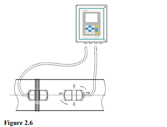
6. Place the downstream transducer on the pipe at the calculated transducer spacing. The installation of a pair of sensors is used as an example. The method of the other pair is the same. See Figure 2.6. Using firm hand pressure, slowly move the transducer both towards and away from the upstream transducer while observing Signal Strength. Clamp the transducer at the position where the highest Signal Strength is observed. Signal Strength RSSI of between 60 and 95 percent is acceptable. On certain pipes, a slight twist to the transducer may cause signal strength to rise to acceptable levels.
7. Secure the transducer with a stainless steel strap or other.
8. Repeat the preceding steps to install another pair of sensors
Post time: Aug-28-2023