
1. For TF1100 clamp on flow transducers, place a single bead of couplant, approximately 0.05inch [1.2mm] thick, on the flat face of the transducer. Generally, silicone-based grease is used as an acoustic couplant, but any grease-like substance that is rated not to “flow” at the temperature that the pipe may operate will be acceptable.
2.Place the upstream transducer in position and secure with a mounting strap. Straps should be placed in the arched groove on the end of the transducer. A screw is provided to help hold the transducer onto the strap. Verify that the transducer is stick to the pipe - adjust as necessary. Tighten the transducer strap securely.
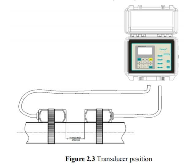
3.Place the downstream transducer on the pipe at the calculated transducer spacing. See Figure 2.3. Using firm hand pressure, slowly move the transducer both towards and away from the upstream transducer while observing Signal Strength. Clamp the transducer at the position where the highest Signal Strength is observed. A Signal Strength (Menu 90) between 60 and 95 is acceptable.
4. If after adjustment of the transducers the Signal Strength(Menu 90) does not rise to above 60, then an alternate transducer mounting method should be selected. If the mounting method was W-mode, then reconfigure the TF1100 for V-mode, reset the TF1100, move the downstream transducer to the new location and repeat step 3.
V-Mount is the STD installation method, it is convenient and accurate, Reflective type (transducers mouthed on one side of the pipe) of installation used primarily on pipe size in the (50mm~400mm) internal diameter range attention transducer designed parallel on the centre line of installing the pipeline.
The spacing value shown on menu window M25 refers to the distance of inner spacing between the two transducers. The actual transducers spacing should be as close as possible to the spacing value. The transducer spacing is from the end of one transducer to another sensor.
The transducer mounting spacing is very important for Transit-time meters, and users need mount transducers exactly according to the spacing distance value M25 displays after users input proper parameter settings. M91 is only for reference, and just keep it within 97–103% value range.
As the above figure shows, the normal transducer spacing refers to the distance between the ends of the two transducers (as the two red lines indicate). And this spacing should be exactly according to the value M25 tells you. Note that this method suits for normal Small, Std. M and Large transducer.
Mounting Transducers in Z-Mount Configuration Installation on larger pipes requires careful measurements to the linear and radial placement of the L1 transducers. Failure to properly orient and place the transducers on the pipe may lead to weak signal strength and/or inaccurate readings. The section below details a method for properly locating the transducers on larger pipes. This method requires a roll of paper such as freezer paper or wrapping paper, masking tape and a marking device.
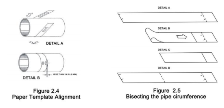
1. Wrap the paper around the pipe in the manner shown in Figure 2.4. Align the paper ends to within 0.25 inches [6 mm].
2. Mark the intersection of the two ends of the paper to indicate the circumference.
Remove the template and spread it out on a flat surface. Fold the template in half, bisecting the circumference. See Figure 2.5.
3. Crease the paper at the fold line. Mark the crease. Place a mark on the pipe where one of the transducers will be located. See Figure 2.1 for acceptable radial orientations. Wrap the template back around the pipe, placing the beginning of the paper and one corner in the location of the mark. Move to the other side of the pipe and mark the pipe at the ends of the crease. Measure from the end of the crease directly across the pipe from the first
transducer location) the dimension derived in Step 2, Transducer Spacing. Mark this location on the pipe.
4. The two marks on the pipe are now properly aligned and measured.
If access to the bottom of the pipe prohibits the wrapping of the paper around the circumference, cut a piece of paper to these dimensions and lay it over the top of the pipe.
Length = Pipe O.D. x 1.57; width = Spacing determined on page 2.6
Mark opposite corners of the paper on the pipe. Apply transducers to these two marks.
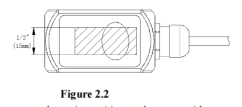
5. Place a single bead of couplant, approximately 0.05 inch [1.2 mm] thick, on the flat face of the transducer. See Figure 2.2. Generally, a silicone-based grease is used as an acoustic couplant, but any grease-like substance that is rated to not “flow” at the temperature that the
pipe may operate at, will be acceptable.
a)Place the upstream transducer in position and secure with a stainless steel strap or other. Straps should be placed in the arched groove on the end of the transducer. A screw is provided
b)Try to help hold the transducer onto the strap. Verify that the transducer is true to the pipe – adjust as necessary. Tighten transducer strap securely. Larger pipes may require more than one strap to reach the circumference of the pipe.
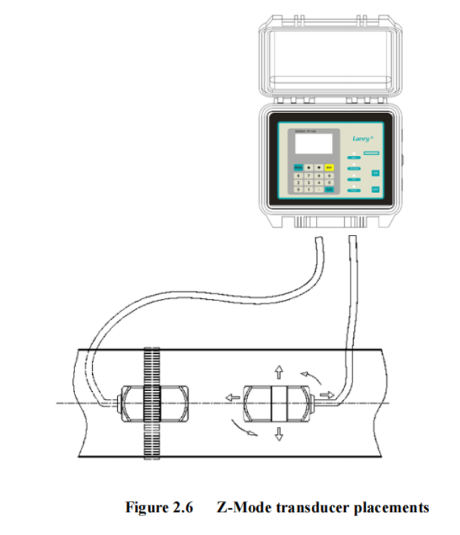
6. Place the downstream transducer on the pipe at the calculated transducer spacing. See Figure 2.6. Using firm hand pressure, slowly move the transducer both towards and away from the upstream transducer while observing Signal Strength. Clamp the transducer at the position where the highest Signal Strength is observed. Signal Strength of between 60 and 95 percent is acceptable. On certain pipes, a slight twist to the transducer may cause
signal strength to rise to acceptable levels.
7. Secure the transducer with a stainless steel strap or other.
Post time: Jun-19-2022